Introduction:
This document describes the configuration of Agilent Gas Chromatography (GC) and GC/Headspace Sampler (HS) modules within Waters Empower and Agilent Instrument Control Framework (ICF). The Agilent PreConfiguration tool is necessary to configure the modules and set up the systems. This tool has been integrated in Empower since Agilent ICF Support v2.2 and can be found in the Waters Empower Configuration Manager.
Note: Waters configuration concept differs significantly from the Agilent configuration concept.
Prerequisites for Waters Empower:
All prerequisites and restrictions related to the installation and usage of the Agilent ICF Support driver integration is included in the Release Notes published by Waters.
The legacy instrument control for Agilent GC and HS modules (e.g. Agilent 7890 GC ICS Version 2.6 or Headspace Control Option Version 3.0) can coexist with the ICF integration.
Note: If “Dual tower support”, provided with “Agilent ICF Support Layer v3.2”, is used the legacy drivers should be removed on both LACE and Client / Citrix Server.
For details please see the Release Notes for Agilent ICF Support provided by Waters.
Prerequisites for the Agilent GC/HS Hardware:
Agilent strongly recommends that the firmware in all Agilent modules are updated to the latest firmware revision. The current firmware is listed on Agilent.com or one could contact the Agilent response center.
It is highly recommended to check and if needed adjust the configuration of the GC and HS hardware (Gas types, Wash vials, Cool Down mode, Syringe size, Loop volume, Vial size (G1888A) etc.) on the instrument via the keypad or touchscreen interface before executing the Pre-Configuration tool.
Ethernet communication is required for all GC and HS modules controlled via ICF. For 6890A and 6890 Plus GCs this may mean that the hardware requires an update with a LAN Accessory Kit from Agilent, part number G2335A.
Use a fixed IP address for the GC and HS modules. DHCP is not recommended. The IP address is set on the GC or HS. To set the GC IP address on the Agilent 8890, 8860 or Intuvo 9000 GC.
- Press Settings on the touch screen control ribbon to bring up the Settings screen.
- Press System Settings. The System Settings screen appears.
- From the System Settings screen, scroll to the Network Configuration area.
- If Enable DHCP is selected, deselect Enable DHCP.
- When prompted, restart the GC.
- Return to the System Settings screen, and then scroll to the Network Configuration area.
- Enter the Host Name in the corresponding field.
- Enter the Gateway number in the corresponding field.
- Enter the IP Address in the corresponding field.
- Enter the subnet mask in the Net Mask field.
- Press Apply.
- When prompted, restart the GC. Your entered changes are now in effect.
To access the GC or HS IP address on an instrument with a keypad, press Options > Communications > Enter.
Verify that all modules are connected and reachable on the network. To do this launch Command Prompt on the computer and type ping xxx.xxx.xxx.xxx where x is the IP address of the GC or HS.
Use the Pre-Configuration Tool to configure Agilent GC/HS modules in Empower 3
1. In the Empower Configuration Manager, click Tools > Agilent PreConfiguration.
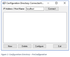
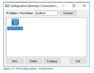
2. A Configuration Directory dialog box will open. Enter the IP Address or Host Name of the LAC/E box that your hardware module is connected to and click Connect. On a Workstation installation or if you are working directly on the Lace the hardware modules connected to, use localhost as the Host Name. Do not enter the IP address of the hardware module here.
3. Once the IP Address is connected, click New to open the PreConfiguration Utility.
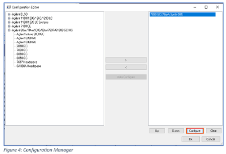
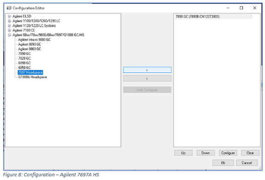
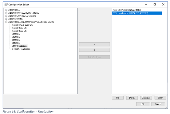
4. In the Configuration Editor dialog box, select the correct GC type from the list of available modules on the left and click the arrow to the right button to add the selected module to right window. Auto Configure is not available for GC, the button will be grayed out.
5. Double -click the module in the right window or select it and click Configure. This opens the configuration dialog box for the selected module.
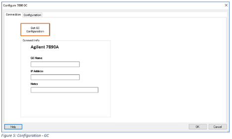
6. Add the IP Address of the GC and click Get GC Configuration. The driver uses the existing connection to upload the actual configuration and settings from the module.
GC Name and Notes are optional fields.
7. As soon as Successful connection to GC – Config available is displayed, the GC has been connected and the configuration is uploaded to the CDS.
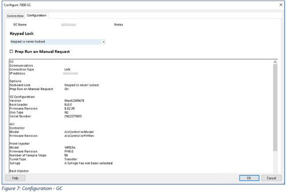
8. After the module configuration information is successfully received by the CDS, the Configuration tab will display the configuration details.
9. Review the configuration and change Keypad Lock and Prep Run on Manual Request as needed. Prep Run on Manual Request should be checked for Agilent G1888A HS and unchecked for PAL-XT, PAL3, and Agilent 7697A HS. It is not very useful for actual manual injections (except for a 6850 GC).
10. Click OK to exit the GC configuration.
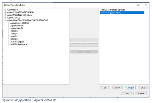
11. If a HS is included in the system repeat steps 4 – 10.
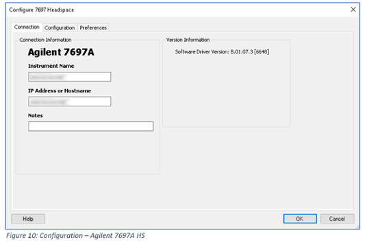
See Figure 8 – Figure 12 for Agilent 7697A HS.
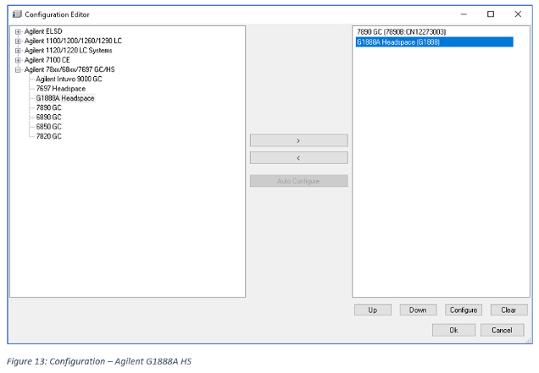
See Figure 13 – Figure 15 for the Agilent G1888A HS.
If a HS is not included proceed to step 12.
Agilent 7697A HS
Click Upload from Module to upload the settings from the module in the Configuration tab.
Use all settings shown in Figure 12 to configure the Agilent 7697A HS. Check both items under Method Editor, select Use standard module actuals coloring, and check Track GC cycle time. Review all entries and click OK to close the dialog box.
Agilent G1888A HS
Tip: Click Upload from Module to upload the Instrument Settings and System Connections from the HS. Make any changes then click OK to close the dialog box.
The Vial size is part of the configuration of the Agilent G1888A HS. The vial size is a method parameter on the Agilent 7697A HS. As soon as the vial size on the Agilent G1888A HS is changed, the GC/HS system must be reconfigured via the PreConfiguration tool.
Vial EPC Connection and Carrier Connection entries are for information only.
12. As soon as all modules are configured and available in the Configuration Editor, you can close the dialog box by clicking Ok.
13. The Configuration Directory dialog box should now include one system, identified by the IP address of the GC. The HS is included in the system and will not be displayed as a separate module.
14. Complete and finish the PreConfiguration procedure by clicking Exit.
Adding a Preconfigured GC or GC/HS System to Empower
This section describes how to add the Preconfigured system to Empower to make it available as a module.
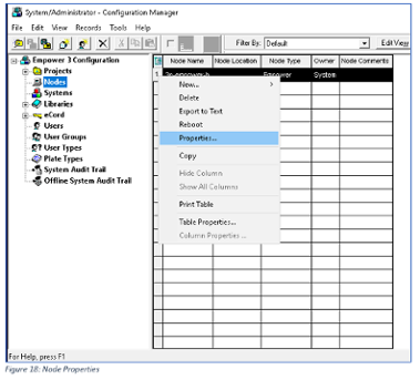
1. Open the properties for the specific node. This can be done by accessing Nodes in the Empower 3 configuration tree on the left side of the window.
On the right side, select the correct Node Name > right-click > select Properties… (see Figure 18).
Alternative: Select the correct Node Name as described before, click File on top left of the main menu of the Configuration Manager window and select Properties.
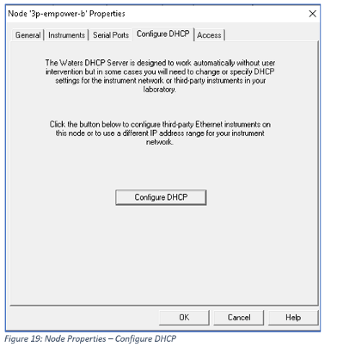
2. The dialog box for the properties of the selected node appears. Select the Configure DHCP tab and click Configure DHCP.
The Waters DHCP Server assigns IP addresses and unique identifier (serial# or names) to Ethernet modules that are attached to a module network card in the acquisition server.
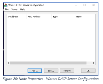
3. The Waters DHPC Server Configuration dialog box appears. Click Add…
4. Add all requested information in the Add IP Address dialog box. (Figure 21)
IP Address: This address must be the address from the previously preconfigured GC.
MAC Address: It is recommended to use the MAC Address of the LAN communication board installed in the GC module, but any other entry should also work. The GC MAC Address is listed in the same menu as the IP address.
Instrument Type: Must be set to AgGC.
Serial Number/Unique Name: Add a unique system name. The serial number of the GC is recommended.
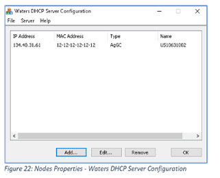
5. Click OK to close the dialog box.
6. Check all the settings for the new system. Click Edit… to make any changes.
7. Click OK to close the Waters DHCP Server Configuration dialog box.
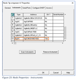
8. Select the Instruments tab and click Scan Instruments. The previously configured system should be displayed in the list of instruments. The OK? status must be Yes. If the OK? status is No, the system should be deleted and reconfigured.
9. Close the Node Properties dialog box by clicking OK.
Adding the GC or GC/HS system to a Chromatographic System in Empower
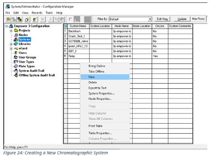
1. In the Empower 3 Configuration tree in the Configuration Manager click Systems.
2. To create a new system, right-click in the area of the right window of the Configuration Manager and select New. (Figure 24)
Alternative ways:
- Right-click Systems from the navigation bar on the left > New > Chromatographic System.
- On the main menu on top of the Configuration Manager select File > New > Chromatographic System.
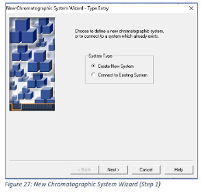
3. The New Chromatographic System Wizard starts with the Type Entry dialog box. Select Create New System and click Next>.
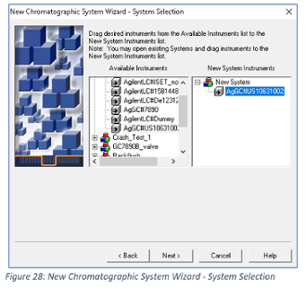
4. Locate the system you will work with in the list of Available Modules and drag and drop the module to the New System Instruments window on the right. Alternatively, you can double-click on the module you want to use.
5. Click Next>.
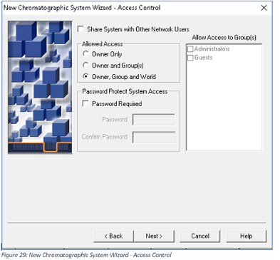
6. Change or set the settings for the access control as needed and click Next>.
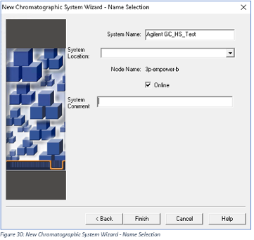
7. Edit and fill the fields in the Name Selection dialog box as needed. System Name is mandatory. Check the Online checkbox to bring the new created system immediately online after the wizard has been finished.
8. Click Finish to complete the New Chromatographic System Wizard.
9. To access the system, it must be Online in the list of systems (Figure 31).
Launch Run Samples to View the Systems Online
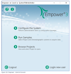
1. Execute Run Samples in the Control console.
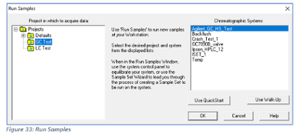
2. Select the Project in which your acquired data should be stored and the Chromatographic System you want to work with and click OK.
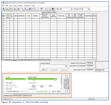
3. The Run Sample application should start, and the selected module should be visible as online (Idle). The Module Status can be shown by clicking View > Control Panels.
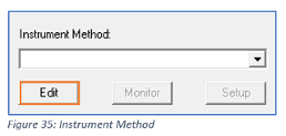
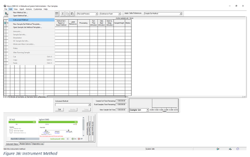
4. Now you should be able to edit the Instrument Method.
or
or you can create a New Sample Set Method…
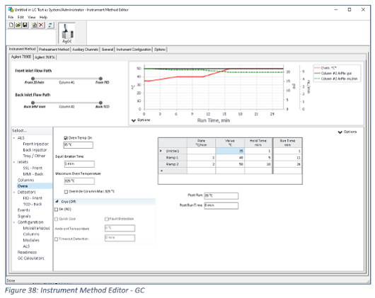
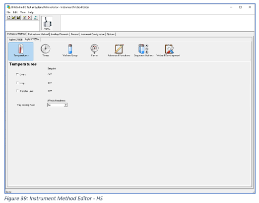
All three procedures above will open the Instrument Method Editor.
See Figure 38 for the GC method editor and Figure 39 for the HS method editor.
If the method parameters should be stored, you must Save or Save as the method. After the method is saved, proceed with running the sample(s).
Keywords: gc headspace, gc configuration, instrument control framework, agilent icf, waters empower, gc configuration in waters empower











-

marshallb
-
Cancel
-
Vote Up
0
Vote Down
-
-
Sign in to reply
-
More
-
Cancel
-

ryoboyle
in reply to marshallb
-
Cancel
-
Vote Up
0
Vote Down
-
-
Sign in to reply
-
More
-
Cancel
Comment-

ryoboyle
in reply to marshallb
-
Cancel
-
Vote Up
0
Vote Down
-
-
Sign in to reply
-
More
-
Cancel
Children