Troubleshooting front inlet flow problems

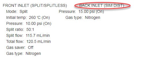
I require technical support for a 6890 GC.  When running a method with a temperature ramp, at the higher temperatures there is an inlet flow shutdown and the GC shuts down.  The upstream carrier pressure is 95 psi which should be high enough.  I notice, when setting up a method, that when I change the pressure for the back inlet, the front inlet pressure changes and may not reach the right setpoint depending on the pressure set for the back inlet.


I tried an "unobtrusive" leak test that I saw on some troubleshooting guide, which suggested going to a splitless flow and seeing if the flowrate in the front inlet was higher than the setpoint which would indicate a flow -- when I followed this procedure the front inlet had zero flow.


I'm wondering since the pressure from the back and front inlets aren't independent and I was not able to get front inlet flow from this test, if that means there is an issue with the flow module, or if anyone has any other ideas. 

Parents
  • Hi mj.hazlett,

    Can you tell me a little more about your inlet parameters? Column dimensions and approximate temp that the inlet shuts down would be useful. Oven ramp rate would be beneficial as well.

    Usually a shut down at higher oven temps indicates that you may have marginal total flow set for the inlet. Split/splitless inlets are designed to work with a minimum of 20ml/min. You can sometimes get away with lower total flow with isothermal or small rates of temp increase.  You are correct that one flow channel (inlet) shouldn't affect the other as they are on separate EPC modules. A supply of 95 psi should be fine as long as its 95psi to the back of the instrument and not meeting a restricted gas trap that would lower the pressure under flow conditions. 

  • The parameters are below; the flow issues start when the oven reaches 200C where the flow is half the setpoint, and the shut down occurs shortly after when the oven is around 220C.


    OVEN
       Initial temp:  50 'C (On)               Maximum temp:  300 'C
       Initial time:  4.00 min                 Equilibration time:  0.50 min
       Ramps:
          #  Rate  Final temp  Final time
          1 20.00      250        6.00
          2   0.0(Off)
       Post temp:  0 'C
       Post time:  0.00 min
       Run time:  20.00 min


    FRONT INLET (SPLIT/SPLITLESS)           BACK INLET (SIM DIST)
       Mode:  Split                            Pressure:  15.00 psi (On)
       Initial temp:  260 'C (On)              Gas type:  Nitrogen
       Pressure:  10.00 psi (On)
       Split ratio:  50:1
       Split flow:  115.7 mL/min
       Total flow:  120.5 mL/min
       Gas saver:  Off
       Gas type:  Nitrogen


    COLUMN 1                                COLUMN 2
       Capillary Column                        Capillary Column
       Model Number:  Agilent 19091J-413       Model Number:  Agilent 19091P-Q04
       HP-5  5% Phenyl Methyl Siloxane         HP-PLOT Q
       Max temperature:  325 'C                Max temperature:  290 'C
       Nominal length:  30.0 m                 Nominal length:  30.0 m
       Nominal diameter:  320.00 um            Nominal diameter:  320.00 um
       Nominal film thickness:  0.25 um        Nominal film thickness:  20.00 um
       Mode:  constant pressure                Mode:  constant pressure
       Pressure:  10.00 psi                    Pressure:  15.00 psi
       Nominal initial flow:  2.3 mL/min       Nominal initial flow:  2.3 mL/min
       Average velocity:  38 cm/sec            Average velocity:  43 cm/sec
       Inlet:  Front Inlet                     Inlet:  Back Inlet
       Outlet:  Front Detector                 Outlet:  Back Detector
       Outlet pressure:  ambient               Outlet pressure:  ambient


    FRONT DETECTOR (FID)                    BACK DETECTOR (TCD)
       Temperature:  270 'C (On)               Temperature:  250 'C (On)
       Hydrogen flow:  40.0 mL/min (On)        Reference flow:  20.0 mL/min (On)
       Air flow:  450.0 mL/min (On)            Mode:  Constant column+makeup flow
       Mode:  Constant makeup flow             Combined flow:  7.0 mL/min
       Makeup flow:  45.0 mL/min (On)          Makeup flow:  On
       Makeup Gas Type: Nitrogen               Makeup Gas Type: Nitrogen
       Flame:  On                              Filament:  On
       Electrometer:  On                       Negative polarity:  Off
       Lit offset:  2.0

  • valentinrusu,

    Thanks for including the document for reference, I did try that inlet leak check; after I complete step 6 the total flow rate is zero. 


    The GC is the only instrument connected to the nitrogen at the moment.  I used to have the source set to 80 psig and increased it to 95 psig when I noticed the issue and it did not seem to impact it.  The max pressure on the FID and TCD are 100 psig, so I don't feel comfortable going much higher...

  • It sounds like from both of your feedback maybe I should try the split vent restriction test.
    For this instrument I have the front column with manual injection to split/splitless, and the back column is attached to a gas sampling valve.  The instructions say to deconfigure the column from the inlet, this would only be for the front column, correct?   I will try this next.


    If it is the split vent line or trap that is restricted, is there a procedure to follow to clean these out?


    Just as a bit more background, this GC has been sitting dormant for months due to a lab move.  The septum has been recently replaced, and I checked the liner o-ring and it was intact.

  • Thanks.

    Is this issue split vent restriction issue related to why the pressures on the front and back inlets seem to depend on eachother?  (ie the back inlet pressure needs to be higher than the front inlet pressure to reach the setpoint pressure, but if the back inlet pressure is set too much higher the inlet pressure overshoots and can't get low enough)

  • I tried the Split Vent Restriction Test... I am not able to set the pressure to zero without the flow being automatically adjusted to zero.  Please advise.

  • By chance is your TCD plumbed to your FID, non destructive to destructive detector configuration? Or using a splitter device of some type? A picture from inside the oven would help. Have you tried the split vent maintenance yet? I would do this even without the result of the testing. Especially if you do not know the maintenance history.

  • Ok, I think we know why one inlet is affecting another. This is not a straight forward basic single inlet to single detector configuration . This is why when you pressurize or change flows one inlet causes a change on the other. That mystery is solved . The GC has been altered and the Sim Dis comment from the method makes sense. I am not familiar with that configuration but can enlist help of a co-worker if needed. Are you going to run this as a simulated distillation application? If not you may benefit from making some changes to the GC as configured. That would go beyond the scope of forum or phone support and would need an Agilent representative onsite. For the time being, the split trap maintenance should take place. Pic above should help, to see the trap canisters, remove the top back cover that stretches across the entire top rear of the GC. Filters are left rear. I pasted a video link that should help. This is a newer style GC, but very similar. https://www.youtube.com/watch?v=vIoHnW5NKBE

    Change the Split Vent Trap - GC Troubleshooting Series - YouTube

Reply
  • Ok, I think we know why one inlet is affecting another. This is not a straight forward basic single inlet to single detector configuration . This is why when you pressurize or change flows one inlet causes a change on the other. That mystery is solved . The GC has been altered and the Sim Dis comment from the method makes sense. I am not familiar with that configuration but can enlist help of a co-worker if needed. Are you going to run this as a simulated distillation application? If not you may benefit from making some changes to the GC as configured. That would go beyond the scope of forum or phone support and would need an Agilent representative onsite. For the time being, the split trap maintenance should take place. Pic above should help, to see the trap canisters, remove the top back cover that stretches across the entire top rear of the GC. Filters are left rear. I pasted a video link that should help. This is a newer style GC, but very similar. https://www.youtube.com/watch?v=vIoHnW5NKBE

    Change the Split Vent Trap - GC Troubleshooting Series - YouTube

Children
Was this helpful?