Troubleshooting front inlet flow problems

I require technical support for a 6890 GC.  When running a method with a temperature ramp, at the higher temperatures there is an inlet flow shutdown and the GC shuts down.  The upstream carrier pressure is 95 psi which should be high enough.  I notice, when setting up a method, that when I change the pressure for the back inlet, the front inlet pressure changes and may not reach the right setpoint depending on the pressure set for the back inlet.


I tried an "unobtrusive" leak test that I saw on some troubleshooting guide, which suggested going to a splitless flow and seeing if the flowrate in the front inlet was higher than the setpoint which would indicate a flow -- when I followed this procedure the front inlet had zero flow.


I'm wondering since the pressure from the back and front inlets aren't independent and I was not able to get front inlet flow from this test, if that means there is an issue with the flow module, or if anyone has any other ideas. 

Parents
  • Hi mj.hazlett,

    Can you tell me a little more about your inlet parameters? Column dimensions and approximate temp that the inlet shuts down would be useful. Oven ramp rate would be beneficial as well.

    Usually a shut down at higher oven temps indicates that you may have marginal total flow set for the inlet. Split/splitless inlets are designed to work with a minimum of 20ml/min. You can sometimes get away with lower total flow with isothermal or small rates of temp increase.  You are correct that one flow channel (inlet) shouldn't affect the other as they are on separate EPC modules. A supply of 95 psi should be fine as long as its 95psi to the back of the instrument and not meeting a restricted gas trap that would lower the pressure under flow conditions. 

  • The parameters are below; the flow issues start when the oven reaches 200C where the flow is half the setpoint, and the shut down occurs shortly after when the oven is around 220C.


    OVEN
       Initial temp:  50 'C (On)               Maximum temp:  300 'C
       Initial time:  4.00 min                 Equilibration time:  0.50 min
       Ramps:
          #  Rate  Final temp  Final time
          1 20.00      250        6.00
          2   0.0(Off)
       Post temp:  0 'C
       Post time:  0.00 min
       Run time:  20.00 min


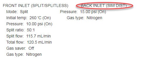
    FRONT INLET (SPLIT/SPLITLESS)           BACK INLET (SIM DIST)
       Mode:  Split                            Pressure:  15.00 psi (On)
       Initial temp:  260 'C (On)              Gas type:  Nitrogen
       Pressure:  10.00 psi (On)
       Split ratio:  50:1
       Split flow:  115.7 mL/min
       Total flow:  120.5 mL/min
       Gas saver:  Off
       Gas type:  Nitrogen


    COLUMN 1                                COLUMN 2
       Capillary Column                        Capillary Column
       Model Number:  Agilent 19091J-413       Model Number:  Agilent 19091P-Q04
       HP-5  5% Phenyl Methyl Siloxane         HP-PLOT Q
       Max temperature:  325 'C                Max temperature:  290 'C
       Nominal length:  30.0 m                 Nominal length:  30.0 m
       Nominal diameter:  320.00 um            Nominal diameter:  320.00 um
       Nominal film thickness:  0.25 um        Nominal film thickness:  20.00 um
       Mode:  constant pressure                Mode:  constant pressure
       Pressure:  10.00 psi                    Pressure:  15.00 psi
       Nominal initial flow:  2.3 mL/min       Nominal initial flow:  2.3 mL/min
       Average velocity:  38 cm/sec            Average velocity:  43 cm/sec
       Inlet:  Front Inlet                     Inlet:  Back Inlet
       Outlet:  Front Detector                 Outlet:  Back Detector
       Outlet pressure:  ambient               Outlet pressure:  ambient


    FRONT DETECTOR (FID)                    BACK DETECTOR (TCD)
       Temperature:  270 'C (On)               Temperature:  250 'C (On)
       Hydrogen flow:  40.0 mL/min (On)        Reference flow:  20.0 mL/min (On)
       Air flow:  450.0 mL/min (On)            Mode:  Constant column+makeup flow
       Mode:  Constant makeup flow             Combined flow:  7.0 mL/min
       Makeup flow:  45.0 mL/min (On)          Makeup flow:  On
       Makeup Gas Type: Nitrogen               Makeup Gas Type: Nitrogen
       Flame:  On                              Filament:  On
       Electrometer:  On                       Negative polarity:  Off
       Lit offset:  2.0

  • By chance is your TCD plumbed to your FID, non destructive to destructive detector configuration? Or using a splitter device of some type? A picture from inside the oven would help. Have you tried the split vent maintenance yet? I would do this even without the result of the testing. Especially if you do not know the maintenance history.

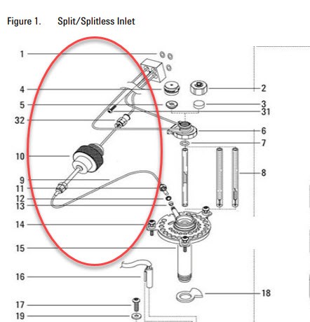
  • Ok, I think we know why one inlet is affecting another. This is not a straight forward basic single inlet to single detector configuration . This is why when you pressurize or change flows one inlet causes a change on the other. That mystery is solved . The GC has been altered and the Sim Dis comment from the method makes sense. I am not familiar with that configuration but can enlist help of a co-worker if needed. Are you going to run this as a simulated distillation application? If not you may benefit from making some changes to the GC as configured. That would go beyond the scope of forum or phone support and would need an Agilent representative onsite. For the time being, the split trap maintenance should take place. Pic above should help, to see the trap canisters, remove the top back cover that stretches across the entire top rear of the GC. Filters are left rear. I pasted a video link that should help. This is a newer style GC, but very similar. https://www.youtube.com/watch?v=vIoHnW5NKBE

    Change the Split Vent Trap - GC Troubleshooting Series - YouTube

  • Without knowing the complete configuration this is a hard question to answer. On the top of the oven, is there a valve or valve oven? Typically the unmodified setup is column from inlet to detector . I assume this GC was taken out of storage or was not in use for awhile. If modified by Agilent, with a serial number I may be able to find a diagram if its valved.

  • Hello James,


    I did this from the GC keypad this time.  The max flow I can set is 200, and the pressure of front inlet is set to zero.  The actual pressure is still dependent on the back inlet.  When I put the pressure of the back inlet to zero as well, the pressure in the front inlet is 0.8.  When I put back inlet to 25, the front inlet pressure reading goes to 9.3.


    Sent from my iPhone

  • I had a look at this photo and this is a custom analyzer rather than a basic GC.  Reconfiguration of what was an expensive custom analyzer goes beyond the scope of the Agilent community. We were able to find the original configuration and this was special order. I would not modify this GC for simple applications. I also see evidence that it may have been modified as the inlet labelling has been changed possibly by another company. If you wish to modify I would suggest contacting your local service Agilent | Contact Us

  • James, here is a photo of inside the oven.


    I ordered the filter and I am trying to clean out the split vent, honestly I am new to the instrument and finding the instructions on the service disk very confusing as I don't know which is the split vent line or where the trap is.....  Is there some schematic or picture of this you can send me?


    Sent from my iPhone

Reply Children
  • Ok, I think we know why one inlet is affecting another. This is not a straight forward basic single inlet to single detector configuration . This is why when you pressurize or change flows one inlet causes a change on the other. That mystery is solved . The GC has been altered and the Sim Dis comment from the method makes sense. I am not familiar with that configuration but can enlist help of a co-worker if needed. Are you going to run this as a simulated distillation application? If not you may benefit from making some changes to the GC as configured. That would go beyond the scope of forum or phone support and would need an Agilent representative onsite. For the time being, the split trap maintenance should take place. Pic above should help, to see the trap canisters, remove the top back cover that stretches across the entire top rear of the GC. Filters are left rear. I pasted a video link that should help. This is a newer style GC, but very similar. https://www.youtube.com/watch?v=vIoHnW5NKBE

    Change the Split Vent Trap - GC Troubleshooting Series - YouTube

  • Without knowing the complete configuration this is a hard question to answer. On the top of the oven, is there a valve or valve oven? Typically the unmodified setup is column from inlet to detector . I assume this GC was taken out of storage or was not in use for awhile. If modified by Agilent, with a serial number I may be able to find a diagram if its valved.

  • I had a look at this photo and this is a custom analyzer rather than a basic GC.  Reconfiguration of what was an expensive custom analyzer goes beyond the scope of the Agilent community. We were able to find the original configuration and this was special order. I would not modify this GC for simple applications. I also see evidence that it may have been modified as the inlet labelling has been changed possibly by another company. If you wish to modify I would suggest contacting your local service Agilent | Contact Us

  • You can certainly try, I just dont know how the valves and plumbing will play into this. With some of these analyzers the back inlet was meant to only provide flow rather than be an active part of the injection path. There maybe someone else who is following this thread that maybe able to  add value.

  • Hello


    Can you elaborate more on this configuration?  So I want it to be single inlet to single detector for the purposes of these experiments... I have one liquid sample I want to analyze on front column with FID and gas sample on back column with TCD.  Is there a way I can make it like that?


    The application for liquid injection is that I want to get concentration of methanol in methanol water solution... I have been diluting this with acetone for analysis.  I was using kind of a blend between ASTM method D7768 and the Agilent Alcohols I method.


    I washed out the copper split vent line like you suggested.  For the trap, while I wait for the new one, should I rinse that as well?


    Sent from my iPhone

  • Hi James,


    I was previously unfamiliar with simulated distillation.  Can you elaborate on the issues of using the GC for applications other than this and why you might recommend reconfiguring?

Was this helpful?