Error after replacing G7111A Quat pump mainboard

Hi all

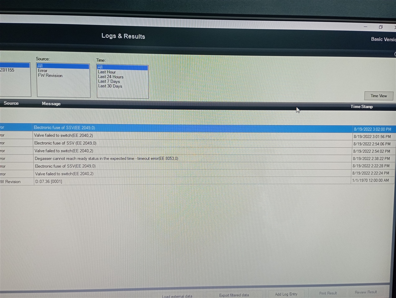
I was replacing a new mainboard (G7111-65810) for G7111A Quat pump. After replacing and power ON, the pump module goes blinking red (resident mode). I try to update the firmware with the latest one, but it error, seen in Lab Advisor as valve failed to switch (EE 2040.2) and electronic fuse of SSV (EE2049.0)

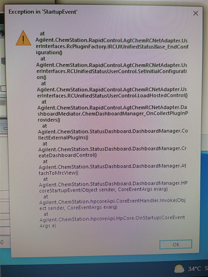
I cannot operate it in chemstation. As i open the chemstation, an error message pop out (just like the picture i post) and there would be no system diagram

Is there a problem with the new mainboard?

Is there a specific protocol for replacing new mainboard for 1260 Inf. II ? Because in older module, replacing the mainboard is plug and play

And why if i try to replace the fusion board, the module become resident mode again?

Parents
  • Did you use the correct board for the A version of the pump? Did you follow the board check and change procedure, which is available in LabAdvisor (FSE license required), followed by an flashing the main and resident firmware? Did you remove/install the main board together with the Fusion board? Those pins can get damaged easily. All this gets shown during the official service training.

  • I order the new mainboard simply by the same part number that is G7111-65810. I did the board check and change: input the module type G7111A and input the module serial number. 

    I only replace the mainboard with the new one (still using the previous fusion board). Or should we replace both the mainboard and the fusion board with the new one?

    Well it really is a downside if those pins can get damaged easily. It would be better with one mainboard design than to split it to fusion board. In my opinion

    And why did it show error electronic fuse of SSV ? Isnt SSV is part of Binary pump?

  • Yes, the part number you went for is fine to a G7111A.

    What I wanted to say: "Those pins can get damaged easily, if not treated correctly". Therefore the Fusion and the main board must not be separated, when the main board is still installed. Like I said earlier, this is shown during the official service training and if you're not trained, you might do things incorrectly.

    No, there is no need to replace the Fusion board in addition to the main board, if the old one is still working. Still the board check and change procedure and the FW re-flash/update is required.

    The screen shot is of not much help, as this comes from the CDS. Please check the information you get from LabAdvisor and if you're an engineer, you should contact Global Service Channel Assist.

Reply
  • Yes, the part number you went for is fine to a G7111A.

    What I wanted to say: "Those pins can get damaged easily, if not treated correctly". Therefore the Fusion and the main board must not be separated, when the main board is still installed. Like I said earlier, this is shown during the official service training and if you're not trained, you might do things incorrectly.

    No, there is no need to replace the Fusion board in addition to the main board, if the old one is still working. Still the board check and change procedure and the FW re-flash/update is required.

    The screen shot is of not much help, as this comes from the CDS. Please check the information you get from LabAdvisor and if you're an engineer, you should contact Global Service Channel Assist.

Children
  • I am now no longer an official engineer for Agilent instrument. Last attend engineer training at Agilent in 2012

    The engineer who installed the mainboard is from an authorized Agilent distributor. I dont know if he had training before

    So there is a chance that the pins are damaged and need to replace the fusion board too?

    Here is the picture from lab advisor

  • If there are damaged pins, they could be either on the main board or on the Fusion board. Could also be a missing cable, a cable installed incorrectly etc. Please ask your authorized Agilent distributor to contact the Global Service Channel Assist group. They would require proper information, such as a System Report and the diagnostic buffers. A cropped screen shot won't so informative.

    Although I don't believe it would work here, something you could try is a so called forced cold start. Turn off the pump, put DIP switches 1 and 6 to the upper position, all others down, turn on the pump and wait 30-60s, turn the pump off again and put all DIP switches back to their original position. All switches down is default.

  • I will ask the distributor to ask Agilent about this problem

    I will try to do the forced cold start

    I will update the results

    Thanks for the suggestions 

Was this helpful?