Reproducibility Issues after system maintenance

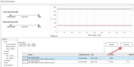
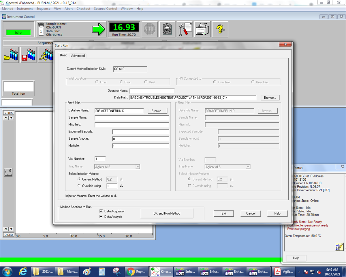
I am using a splitless method to analyze a solution of a material that contains non-volatile polymer and volatile monomer I am running a sequence in which use one method to  volatalize and analyze the monomers and a few  high boiling solvents followed by a second method that degrades the polymer and removes it. I can see that method 2 is pretty effective in cleaning out the liner from the polymer and resulting contamination. We tuned the method untile we had very nice overlaying chromatograms and a very good calibration result.

Then I replaced the filament, the guard column and the MS transferline (both fused silica, deactivated) and all the the connections and ferrules from these to the MS, the PUU (which is used to connect to the analytical column on both sides) and the inlet. After that the calibrations still look fine (area ratios of standard to volatile components), but the overlays don't look good anymore. I even observe shifts in retention time.

When I use split methods for other materials, the overlays look much better.

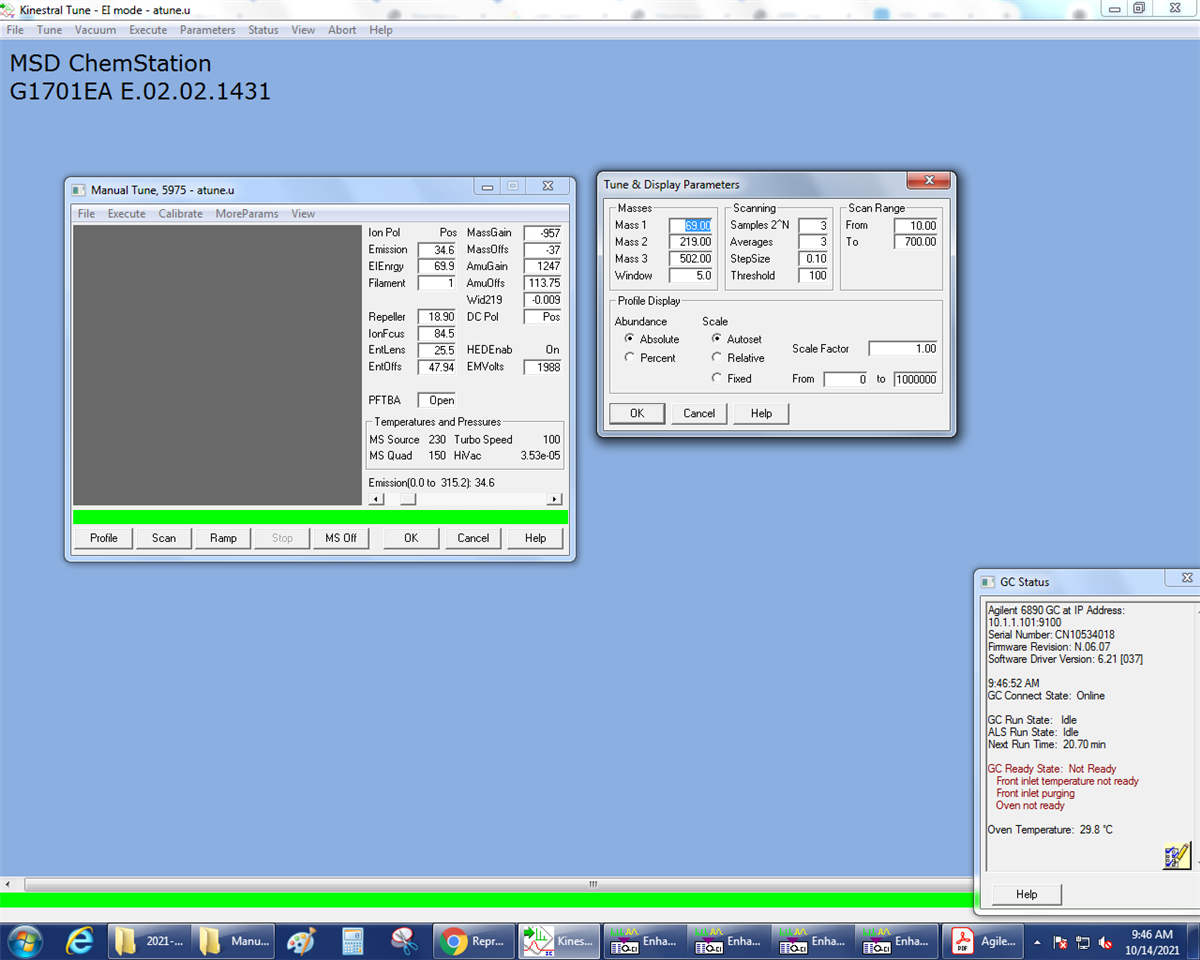
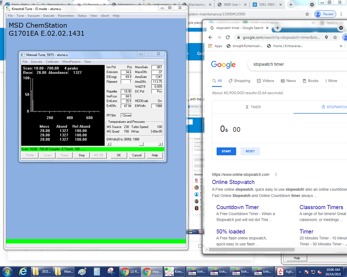
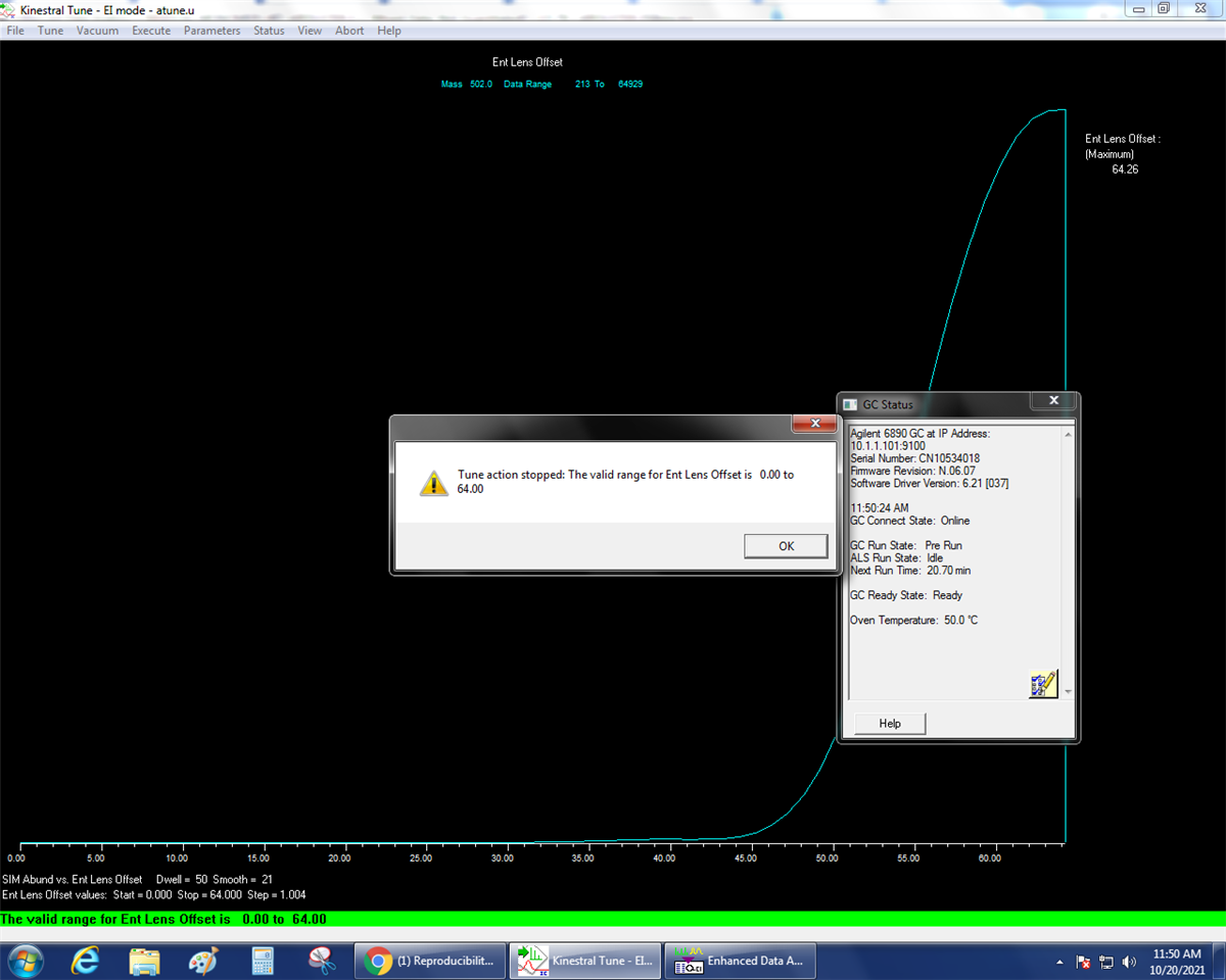
There is no leak based on the tune and the tune looks very good in general. 

I replaced the liner+O-ring, septum and syringe step by step. Still the same issue.

I also just recently replaced the vent line filters.

A consultant of ours suspects the vent valve to maybe not seal properly. Also, I was wondering if it could be the gold seal that needs to be replaced. 

Also it would be great if someone could explain to me a bit more how the sample is injected and volatalized and then released from the inlet in a split/splitless mode. How long is the material heated and not released in the inlet, How long does the vent valve open before it closes again? How far does the syringe go into the liner? Is there a part of the liner that is not heated as much or is the whole liner heated homogenously in the inlet?

My system is an Agilent GC 6890N - MS 5975C. 

I used both of these liners: https://www.agilent.com/store/productDetail.jsp?catalogId=210-4004-5, https://www.agilent.com/store/productDetail.jsp?catalogId=210-4022-5 I know they say split, but I was told they both work for splitless as well and since I have some split and some splitless methods that worked pretty well for us.

Thanks. Bettina

Parents
  • Please read up on split and splitless along with inlet maintenance in the GC manuals. 

    There are many resources on Agilent.com and here on the Agilent Customer Community.

    Maintaining Your Agilent Split/Splitless GC Inlet

    Maintaining Your Agilent Split/Splitless GC Inlet - same title, different presentation!

    Understanding the GC Inlet. Which one is more appropriate for your method? (agilent.com)

    (+) Column Installation - Split/Splitless and Multimode inlets =and= SQ and TQ MS transferlines - Files - GC/MS - Agilent Community

    There are some easy questions to start with.  What is your column configuration?  Is it set properly in the software?  You have a guard column, then two columns with a PUU and going to vaccum in the Mass Spec, is the software and method configured properly?  Does column 2 have about 0.1 to 0.2 ml/min MORE than column 1?  This is necessary so that there is always positive flow from the PUU supply so that sample can't go up the PUU gas supply line.    What is your splitless  Purge ON time? What is your inlet temperature and initial oven temperature and initial oven hold time?

    The cross gold seal is not necessary.  The cross seal is only required if you are running in modes with very high inlet flows, like split over some few hundred ml/min, or have samples with so much residue that collects on the gold seal that it can become clogged  (this would mean that you should do dramatically more inlet maintenance). 

  • Thank you very much. Will work through this. I am not totally sure about the column installation. Our system is set up in a way that the flow that goes though the sequence of guard column-PUU-analytical column-PUU-MS Transfer Lines is viewed as one column as far as I understand, so there is only one column and I cannot set the gas flow differently for the different parts of it as it goes from the inlet into the guard column which is connected to analytical column (through 1st PUU), which is then connected to the MS transfer line (through 2nd PUU) and then to the MS. All 3 columns have the same dmensions. Guard column and MS transfer line ar deactivated fused silica. Maybe I need to reconfigure that. I'll look into that using the resources you shared.

    And yes, we are injecting a polymer that is non volatile and gets stuck on the liner. It is possible that some of that is collecting in the liner as even burn-outs of inlet and column do not fully get rid of residual peaks.

    The column has been used for a loooong time and this material has been injected many times over these past few years. We had a PM done by Agilent last year and I'm pretty sure they cleaned the inlet, but since then we did lots of development work which involved the injection of non-volatiles and compounds with very high boiling points of which I also see impurities in the blanks.

    I may have more questions once I went through all the material you shared

  • I think I understand what you mean and I used the wrong term. We actually have this Union: https://www.agilent.com/store/productDetail.jsp?catalogId=G3182-60581&catId=SubCat2ECS_896718. It is not a PUU, but a UU. Correct? Sorry, I am not an expert (as you can see :-))

    I'll sent all the info you asked for tomorrow.

  • A PUU is a Purged Ultimate Union and has flow. The UU is an Ultimate Union - a connector.  If you have three column pieces joined by UU, just make sure that the software knows how long the total is.   

    The easiest way is to calibrate the column.  It can be done in manual tune by watching, or by setting up a run and using the resultant chromatogram.  

    In Manual Tune, set up repeat profile of 28, 28, 28 -- nitrogen.  With the filament on and the PFTBA off, inject 3 uL of air and measure the time it takes for the nitrogen peak to come out to the nearest second.  Write that number down.

    In a run, setup the method with 0.0 minute solvent delay, scan 10-100, inject 5uL 20:1 split, and put an empty vial into the autosampler.  The resultant chromatogram should have a peak. Integrate it and write down the retention time.

    In the GC Edit Parameters page, Configuration, Columns, Choose the column installed so that it is highlighted in blue and then click on "Calibrate".

    This window comes up:

    Then you choose "If unretained peak holdup time is known --- and click on "Calc Length..."

    Enter the Holdup Time of an Unretained Peak, click elsewhere in the window or hit tab and you'll see the calculated length.  Select OK, OK, and then the updated calibration should be entered.  

    The benefit is that if you cut off a bit, you can do this test again and it will set the proper pressures for the required flow for the new length.  Calibrating the columns makes it easier to keep your retention times the same over time with column changed and column maintenance.

  • Hi Paul, How do I set up the repeat profile of 28, 28, 28? Do I enter it as mass 1, 2, 3?

    What method do I load when I inject 3 uL of air? I would load an empty vial and select 3 uL Injection volume, but what should the method be? 

Reply Children
Was this helpful?