Air Leak in GC/MS located at the transfer line, unsure how to proceed

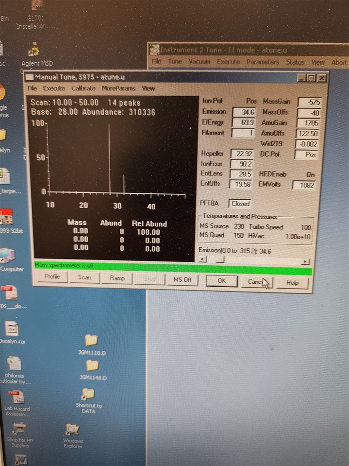
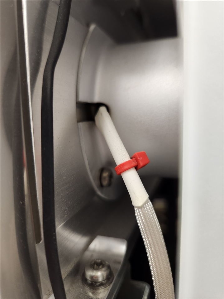
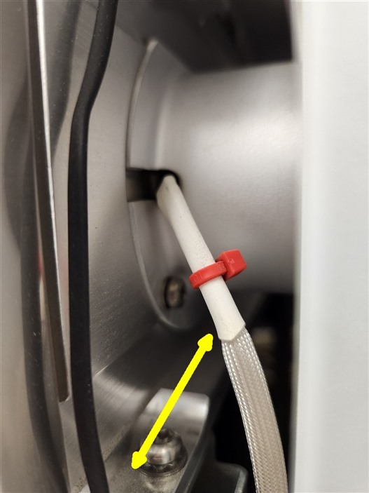
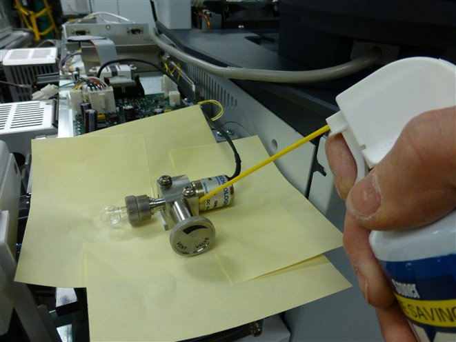
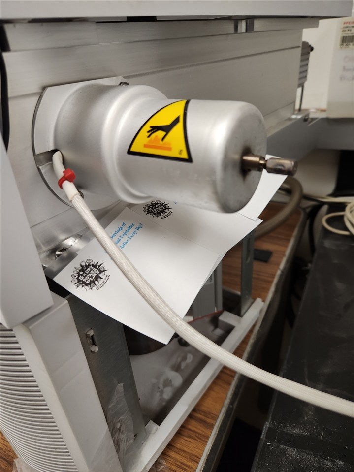
The system we are using is a 6890N GC coupled with a 5975C MSD.  After a recent power outage we pumped the system down and discovered a major air leak with Nitrogen being roughly 50% of ion 69 and Oxygen being 13% after waiting 24 hours from the pump down.  We scanned from 0-100 with the manual tune and used a flow of Argon gas to test for air leak locations, and found that the usual locations were not showing a leak.  We tested: GC/MS interface nut, Vent valve area, MS side plate, foreline pump and hoses, as well as the GC injector and nuts on the GC portion of the system.  The only location where we saw Argon in the scan was where a white cord is connected to the MS transfer line (I've attached a picture).  No other location around the transfer line or anywhere else in the system is showing a leak.  This is a new one for me and I'm unsure what the repair is.  Any help would be appreciated.

Sean Halloran

UC Riverside

  Manual Tune Scan 0-50Location of Air Leak

Parents
  • Hi Sean...I think I've touched that particular instrument a long time ago.   Gary - 50% 28 and 13% 32 after 24 hours is quite a big leak, maybe not massive but certainly needs fixing.

    If the system worked fine before it was cooled off for a power fail and didn't after it was heated up, the usual suspect is the transferline nut/ferrule in the GC oven.  The nut is brass and the part it screws onto is stainless steel.  When the oven temperature is much different than the transferline temperature, there is differential expansion of those dissimilar metals.  When cooling it off for a power fail, the nut in the oven cools off first and then the transferline cools and somewhere in there the ferrule cools.  All of those parts contract at different rates, too.  If you just pump it down and heat it up the seal is just different. It may or may not leak. 

    I would first try to tighten it the smallest possible amount.  Too many of those nuts are overtightened. We even have customers strip the stainless steel transferline!  The nut only needs to be tightened to about 4 inch-pounds. You're only sealing against 14.7 psi up against a very small total sealing surface.  If the leak is still present after that I would vent it and remove/reinstall the column to the proper distance with a new nut and the proper long graphite/vespel ferrule installed with the narrow end into the nut. see:    (+) Column Installation - Split/Splitless and Multimode inlets =and= SQ and TQ MS transferlines - Files - GC/MS - Agilent Community

    There is an O ring between the transferline flange and the vacuum manifold.  They never leak...until they do.  It is incredibly rare for a leak there to just start, but that instrument is pretty old. The transferline itself has full thickness brazes that are tested to 10^-8 at the factory. Those brazes don't fail unless there's an unlikely thermal runaway or the environment is so acidic that there are other problems, too. 

    Next time it's vented replace the vent valve O ring as well.  Also remove the analyzer door O ring, swab out the O ring groove with a solvent-dampened swab, wipe the O ring with a lint-free cloth, and reinstall it.  It's old, too, and should probably be replaced if it hasn't in the last couple of years.

    and let us know how it goes.

  • Hi Paul....Yes, you almost certainly worked on this instrument and Jocelyn was hoping we would be able to get a reply from you!

    I should clarify a few points in case that changes your suggestions.  First, I should mention that the power outage was scheduled, so I had properly vented and cooled the instrument before-hand.  I'm also not entirely sure the air leak only appeared AFTER the new pump down as the instrument has been on for some time but samples had not been run on it in quite some time, so it's possible the air leak started before we vented and pumped down the machine and I only just noticed it now.

    I plan to follow your suggestions and remove the column anyway to confirm the leak is happening on the MS side and not anywhere in the GC.  However, I want to re-iterate that we heavily tested the area around the interface nut with our Argon stream and saw absolutely no indication that the leak was happening there.  We also tightened the nut slightly and re-tested and saw no change in the air leak.  The ONLY location where we saw Argon in the scan was when the stream of gas was placed near the transfer line heater and sensor cord as pictured. 

    So with that in mind, if resetting the column into the transfer line with a new ferule and nut does not fix the issue and we continue to see the leak when streaming Argon near the transfer line heater and sensor cord, what are the next steps we need to follow?  I have memories of the braze on a transfer line failing when I was in Jim Tumlinson's lab back in the early 2000's, so I know it can happen, but I was not the technician who fixed it back then, so I'm not sure what the repair options are.  Can you share the part numbers for the transfer line and O-ring for a 5975C MSD?

    Thank you for your answers thus far, and for any further advice.

    Sean Halloran

    UC Riverside

  • Thank you for the reply.  I was curious if anyone else had any angles to test before I order the new transfer line braze?  I think at this point, that's the only part left that could be the source of my leak.

  • It is incredibly rare to have the metal of the transferline develop a leak without torque damage to the column end.  The only brazes are at the attachment flange and at the end near the column - there are no other connections in the middle of the transferline braze on EI only systems.

    Here's something to try.  Put a row of post-it notes stuck on the manifold below the transferline and leak test again.  Argon is heavier than air and so maybe the leak is lower than the transferline down near the pump or rough pump hose.  A row of large post-it notes across at the yellow arrow will make a barrier that may change the way it responds.

    Where to place post-it notes

    I've done that around the PFTBA valve when I thought the leak was there only to find out that the leak was the side plate O ring and the air duster spray was going there, too.

    Post it barrier around PFTBA valve

  • Hello,

    I figured I'd update this thread with the final conclusion to the problem.  As you requested Paul, I placed the post-it notes underneath the transfer line and tested whether the argon gas was being pulled "down" into a leak below the notes or whether it was occurring at the transfer line.  When the placing the argon flow above the notes I still saw the leak, but when placing the flow below the notes the leak was not present.  I moved the argon flow around the entire machine including the back and very bottom and saw no argon ions in the scan.

    So, at this point I finally decided to remove the old braze and replace it with a new one.  I did this yesterday, and the air leak is completely gone.  Placing the argon flow next to the same place on the machine now shows no argon ion, and the high nitrogen and oxygen counts are now also gone.  I believe I can now say with a fair amount of confidence that this part can break over time and that it should be brought up as a potential source of air leaks more frequently than it currently is.

    In any case, the air leak is now gone and this problem is solved.  I hope this thread can be useful for others who are seeing the same problem as me.

  • Good news!  Happens, just quite rare in the entire population of Agilent mass spectrometers. Sorry it happened to yours!  The part gets replaced fairly often as too many operators overtighten the column nut, even to the point of bending it or stripping the threads.

    Could I get the old part for analysis?

  • Paul, yes, I'd be happy to send the part to you.  How should I go about doing it?

Reply Children
No Data
Was this helpful?