

Do you know about the maelstrom of molecules, atoms, ions, and electrons that are going on inside a GC/MS Electron Ionization ion source?
The molecules streaming out of the end of the column in molecular flow come out at approximately the speed of sound in the carrier gas used, so for helium ~3,191 ft/s (973 m/s, 2,175 mph!)) and for hydrogen ~4,330 ft/s (1,320 m/s, 2,952 mph!). Most GC/MS applications are run in Electron Ionization (EI) mode where electrons with their negative charges traveling at 1.67% of lightspeed (11.2 million mph = 70 eV) fly past the sample molecules disrupting them and they fragment. Sometimes it takes many electrons passing for the molecules to fragment. Some fragments are unstable and fall further apart. Sometimes the fragments interact and cause other rearrangements. This all happens at a nearly unimaginable short time scale. Positively charged fragments are sent towards the mass filter, typically a quadrupole, and focused to maximize the number that enters. That’s what an Electron Ionization Ion Source does.
Agilent currently has six types of EI Ion Sources available.
- The Stainless Steel source is the option that has historically been available on all GC/MS systems and provides performance similar to previous Agilent MSD instruments. It will provide results consistent with older systems without needing software updates. It is the lowest cost option. It is available in 597Xx Single Quadrupole systems.
- The Inert source has parts made from a proprietary metal formulation that provides identical overall performance as the Stainless Steel source while eliminating possible issues with active compounds that are most likely to bind to non-inert surfaces. It is available in 597Xx Single Quadrupole systems.
- The Extractor source has improved ion transmission compared to the Stainless Steel or Inert sources while also being inert. It is available in 5977x Single Quadrupole and 7000x Tandem Quadrupole systems.
- The HydroInert source is an Extractor source with a proprietary coating that reduces hydrogenation or dechlorination while running hydrogen carrier gas, which is required when using this source. It is available in 5977x Single Quadrupole and 7000x Tandem Quadrupole systems.
- The High Efficiency Source (HES) has dramatically improved ion transmission compared to the Extractor ion source. It is available in 5977x Single Quadrupole and 7010x Tandem Quadrupole systems.
- The Low Energy-EI source (LE-EI) used exclusively in the 7250 GC Q-TOF can run like the High Efficiency ion source and can also be used in Low Energy mode, which allows for more specificity by reduced fragmentation. It is only available with this system.
These ion sources can be separated into two main types: orthogonal and axial. The orthogonal EI ion sources, SS/Inert/Extractor/HydroInert, have the electron beam 90° to the ion path.
The orthogonal ion sources can be further separated. The Stainless Steel and Inert sources are functionally identical except that critical parts of the inert source are made of an inert metal. This reduces breakdown of active compounds that are most likely to bind to less inert surfaces like Stainless Steel.
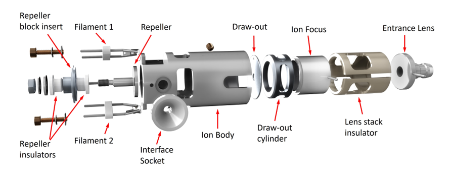
Stainless Steel/Inert Ion Source
The Extractor and HydroInert ion sources use what at first appears to be the same design but has a controllable extractor lens in place of the drawout plate and drawout cylinder. These sources can be tuned using Autotune so that sensitivity is essentially the same as with the Stainless Steel or Inert ion sources. They can also be tuned using Etune, extraction tuning, which changes the way voltages are applied to the repeller, ion body, and extractor lens to focus more ions into the quadrupole without any physical changes. This tuning significantly increases overall system response. Critical parts of the Extractor source are made of inert metal.
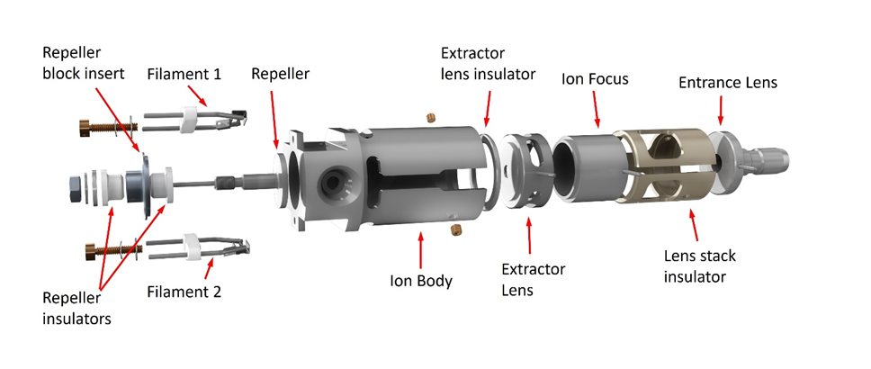
Extractor/HydroInert Ion Source
The HydroInert Source uses the same Extractor source design, but critical inert metal surfaces are also coated with a material that reduces hydrogenation and dechlorination reactions that can happen when hydrogen carrier is used. The HydroInert Source must be used only with hydrogen carrier gas.
HydroInert Ion Source
The axial EI ion sources, HES, and LE-EI, have the electron beam aligned to the ion path. This alignment and the shapes of the ionization chamber and focusing elements results in higher ion transmission than the orthogonal source design, as much as twenty times more.
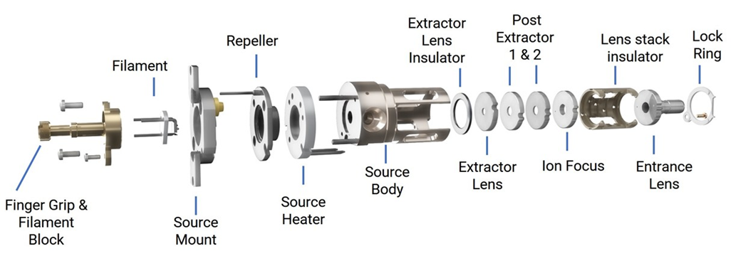
High Efficiency/LE-EI Ion Source
Which source will be best for your application? There are many questions to be considered.
Sample Type. Your compounds:
- Are totally unknown?
- Are a wide variety of possible compounds?
- Are very stable, like many hydrocarbons?
- A concern as some may be active but you aren’t sure?
- Are highly chemically active, like pesticides?
- Are highly chemically active and you will be running hydrogen carrier gas?
- Require lots of prep/cleanup?
- Decompose with temperature?
- Are volatile?
- Are not volatile? – must be derivatized?
Analytical needs:
- Is your analysis screening samples for other tests?
- High library search match results against commercially available libraries
- Quantitation over a wide range of concentrations – linear range or dynamic range
- You need to use a method that was developed on older systems
- Must meet required tuning criteria like BFB or DFTPP
- Hydrogen carrier gas
- Wide range of optimal column flow rates
- Stable results over long periods of time
Concentrations or amounts:
The word “sensitivity” is often used to describe an instrument’s capabilities. For this discussion it is better to consider the concentrations or amounts that need to be measured.
Milligram = 10-3 g > microgram = 10-6 g > nanogram = 10-9 g > picogram = 10-12 g > femtogram 10-15 g > attogram = 10-18 g
1% = 10,000 ppm > 0.1% = 1000 ppm > 0.01% = 100 ppm > 0.001% = 10 ppm > 0.0001% = 1 ppm
- 1000 ppm = one gram per liter = 1 milligram per milliliter = 1 microgram per microliter = 1 part per thousand
- Ocean water is 33-35 grams per liter of dissolved salts = 35 parts per thousand = 35,000 ppm
- 1 ppm = one part per million = 1 milligram per liter = 1 microgram per milliliter = 1 nanogram per microliter
- 1 ppm = 1.66 inches (42.195 mm) of a marathon
- The odor threshold for chlorine is about 0.3 ppm
- 1 ppb = one part per billion = 1 microgram per liter = 1 nanogram per milliliter = 1 picogram per microliter
- 1 ppb = 2.5 milliliters in a regulation Olympic swimming pool
- Methyl mercaptan – a natural gas odorant – has an odor threshold of about 1 ppb
- 1 ppt = one part per trillion = 1 nanogram per liter = 1 picogram per milliliter = 1 femtogram per microliter
- 1 ppt = the area of a compact disk compared to the area of California, Oregon, Washington, plus Nevada!
- 1 ppt = the aroma threshold of 2-methoxy-3-hexylpyrazine, the green bell pepper smell
- 1 ppq = one part per quadrillion = 1 picograms per liter = 1 femtogram per millillter = 1 attogram per microliter
- 1 ppq = 1 gallon (3.785 L) poured into Lake Michigan
- 1 ppq = 2/3 of a sheet of A4 paper compared to the surface area of North and South America
- 1 ppq = 1 inch of the distance to the Voyager Space Probe
The amount that should go into the column and detector is a critical consideration for a robust analysis. Too much total sample and too much of each individual peak injected can cause column overload, detector saturation, and incorrect data. Too much injected results in increased inlet, column, ion source, and pump maintenance. Inject the smallest volume of the lowest concentration of the cleanest sample possible.
GC/MS detector output in scan mode is shown as a spectrum. This is a graph with the Y axis, called counts or abundance, which is the sum of each fragment’s ions that reach the electron multiplier, charted against the mass-to-charge ratio, which for most ions fragments are its mass. Ion fragments are talked about like “188.1 is 5,386,522 counts” or “152 is 1,105,920 abundance.” These spectra are both p-chlorobiphenyl, peak 3 in the 05970-60045 sample used in Proving Functionality.
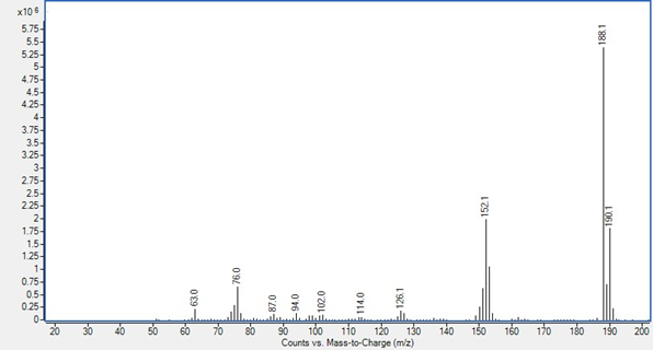
Counts from a 7010B triple quadrupole system from MassHunter Data Analysis
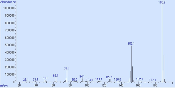
Abundance from a 5977B SQ system from MSD ChemStation Data Analysis
The maximum abundance per ion on Single Quadrupole instruments is approximately 8.4 × 10⁶. To work within the optimal linear range of the electron multiplier no individual ion fragment should exceed 2.0 × 10⁶ counts.
The maximum abundance per ion on TQ instruments is approximately 1.7 × 10⁸. To work within the optimal linear range of the electron multiplier no individual ion fragment should exceed 2.0 × 10⁷ counts.
Stay tuned for the next installment.
DE85992361
.
.
.
-

Ekka
-
Cancel
-
Vote Up
0
Vote Down
-
-
Sign in to reply
-
More
-
Cancel
Comment-

Ekka
-
Cancel
-
Vote Up
0
Vote Down
-
-
Sign in to reply
-
More
-
Cancel
Children