

Part 1 included many questions and some answers about the maximum abundance that should be detected at the electron multiplier. Another important consideration is how much sample should go into the column.
See Which Electron Ionization Ion Source? Part 1 of 4
Inject the smallest volume of the lowest concentration of the cleanest sample possible. The less sample that goes into the column, the less routine maintenance must be done on your GC inlet, GC column, the MS Ion Source, MS vacuum manifold, and MS pumping system. The less sample that goes into the column, the longer the time required between routine maintenance.
The smallest peak of interest in the lowest concentration standard only needs to have a signal that is three to five times the average baseline noise. The largest peak of interest at the highest concentration must not be so large as to overload the GC injection port and column stationary phase, or the MS ion source, detector, electronics, and software. A clean system has lower average baseline noise and so can reproducibly see smaller peaks. An MS ion source that makes more ions and has higher ion transmission into the quadrupole means that the MS can detect smaller amounts/concentrations of peaks coming out of the end of the GC column.
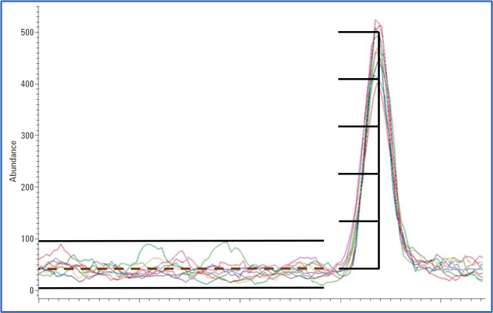
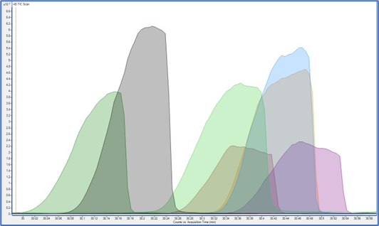
Figure 1 - Three to Five Times the Average Baseline Noise Figure 2 - Incredibly Overloaded Peaks
There are many variables that can be changed to get optimum and robust results.
Before the Mass Spectrometer:
- During sample preparation, you can vary the dilution, the concentration/amount, the range, and the cleanup.
- At the injection port, you can vary the method of sample introduction, the volume/amount injected, the inlet type, the inlet mode, and more.
- With the column you can choose the stationary phase, stationary phase film thickness, column inside diameter, and column length.
At the Mass Spectrometer, there are fewer variables. The optimum flow into the ion source is a narrow range because of instrument design and physics. The EI sources were designed around 1.2 ml/min of helium carrier gas. They work best in the range of 0.8 to 1.4 ml/min of helium carrier gas. With hydrogen carrier gas, they work best at about 60% of those flows, 0.5 to 1.0 ml/min. Higher and lower flows than this range results in tradeoffs with all ion sources and those tradeoffs are bigger with the HES due to the physical design. Higher and lower flows will alter the spectral tilt, which is the relative abundances of lower molecular weight and higher molecular weight ion fragments. This can affect library search match quality, calibration linearity, and overall system performance.
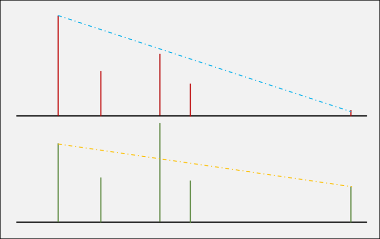
Figure 3 - Spectral Tilt Example
Ion source temperature also affects the spectral tilt by reducing the relative abundance of the higher masses. Higher ion source temperature will keep the ion source cleaner for longer, though, so giving up some high mass relative abundance is nearly always a smart tradeoff. Remember that there is a significant boiling point depression under vacuum. 700 °C boiling point at 1 atm is only ~315 °C in a vacuum. The default 230 °C ion source temperature is great for meeting installation specifications but running at 275° to 300 °C is arguably better for most applications. The quad never needs to be hotter than 175 °C.
Too many molecules in the ionization chamber at any one time can result in saturation. Many ions or many electrons in close proximity, even in a vacuum, create a space charge.In EI mode, too many positive ions too close together repel each other. This happens in the ionization chamber for all compounds, including the ones that are not being analyzed. This means that if too much sample, or too much sample and matrix and analyte protectant and column bleed and air from a leak is coming out of the column and it is all being ionized together the ionization can be suppressed. If there is too much stuff in there, the ions aren’t repelled normally or not focused properly or don’t enter the quad in a tight beam to be filtered correctly. If the system is running SIM or MRM and the method is not looking at all of the other stuff that is coming out while the peaks of interest are coming out, there may be unseen issues. It’s important to run a Scan, SIM/Scan, or MRM/Scan method on those systems to see what is not being looked for regularly. Good chromatography will reduce issues.
Space charge can also alter the way the ions are filtered which can change mass assignments and spectral fidelity. At the detector, the high-energy dynode (HED) and Electron Multiplier (EM) can be overloaded, and the signal is less. When this starts to happen, the result is often seen as a calibration curve that starts to flatten out at higher concentrations. This is also compound dependent.
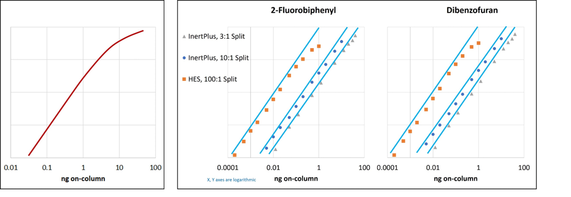
Figure 4 - Example Exaggerated Cal Curve Tailing Example of More Subtle Realistic Curve Tailing
The peaks in the incredibly overloaded peak example are shark-fin shaped, tilted to the right, due to column overload, a different subject, but the ugly shaped tops are MS overload. They are probably much bigger but there’s no way to find out. This data is invalid. Unusable.
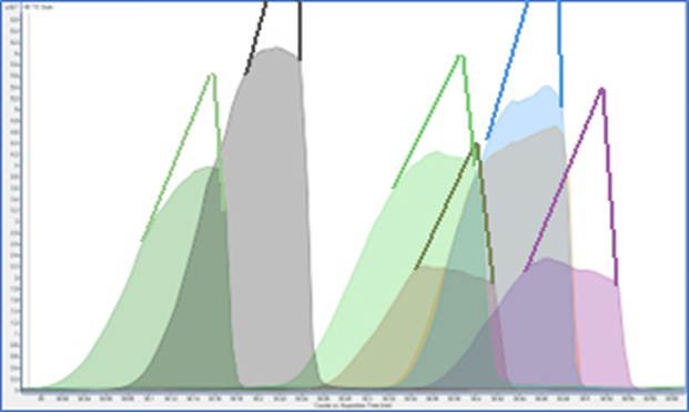
Figure 5 - Invalid Data with Guesses Drawn In
One simple variable that can be used to help control overloading on the orthogonal sources is the diameter of the hole in the Draw Out or extractor lens; 3, 6, or 9 mm. The larger holes reduce ion transmission into the quadrupole. These give up maximum ion transmission for a dynamic range that is still linear at higher concentrations. The 9 mm extractor lens is the default one shipped installed in the HydroInert Ion Source and that size is highly recommended for all systems running hydrogen carrier gas. Start with the largest diameter and only change to a smaller one if the smallest peak in the lowest concentration standard can’t be seen. If that smallest peak is > 3–5 times the average baseline noise, don’t change to a smaller diameter hole. Due to HES design a larger size extractor lens hole doesn’t have the same effect.
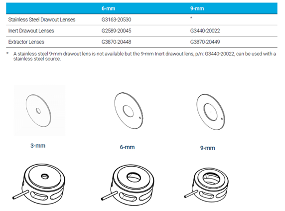
Figure 6 - Available Draw Out and Extractor Lenses
- The absolute maximum abundance output per ion by the electronics on Single Quadrupole instruments is 8,388,096 counts. To stay within the linear range of the electron multiplier, it is recommended to have each individual ion lower than 2.0 × 10⁶ abundance.
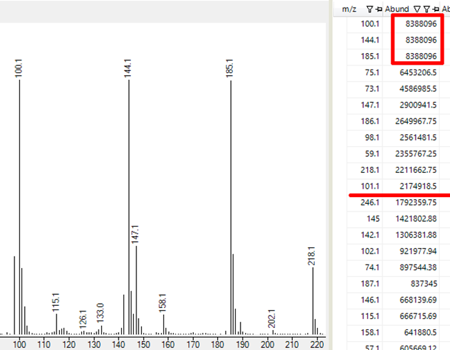
Figure 7 - The Largest 11 Ions Are Too Big
- The maximum abundance per ion on TQ instruments is approximately 174,218,080. To stay within the linear range of the electron multiplier, it is recommended to have each individual ion lower than 2.0 × 10⁷.
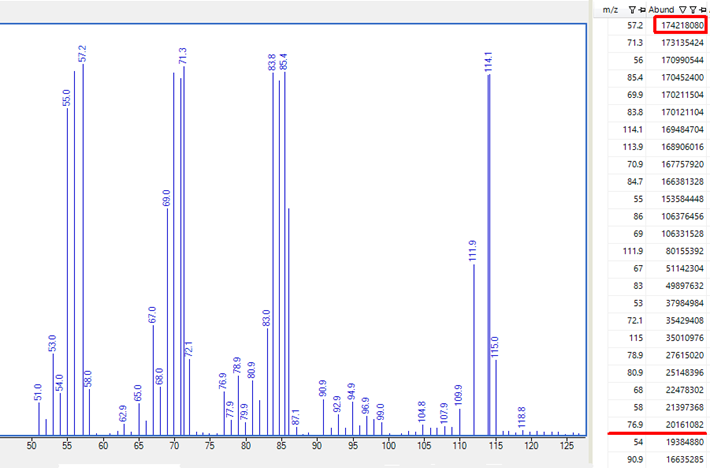
Figure 8 - The Largest 24 Ions Are Too Big
Stay tuned for the next installment - coming soon.
DE85992361