

What is a “High Nitrogen” Value and How to Identify Possible Causes and Solutions
Air is 78.09 % Nitrogen and 20.95 % Oxygen or approximately a 4:1 ratio.
Nitrogen in the MS ion source significantly reduces the sensitivity. You would think that using nitrogen as carrier gas would be a great idea. Nitrogen is readily available, inexpensive, and relatively inert. Nitrogen’s ionization characteristics result in approximately nine times more charge than helium. This causes a high ion‐source space‐charge – too many ions too close together repel each other. Using nitrogen is about like using 10.8 ml/min helium instead of the recommended 1.2 ml/min. It reduces the GC‐MS EI sensitivity by about 20 times.
Oxygen exposure at an elevated temperature will cause permanent column damage, retention time drift to shorter retention, and increased inlet active sites. As little as 10 ppm of Oxygen going through your analytical column will damage it. The amount of Oxygen present determines the rate of damage to the stationary phase, as will column phase type and oven temperature. The damage mechanism is catalytic since each oxygen molecule has the chance to participate in several reactions as it works its way through the column. The damage is cumulative.
Every column manufactured by Agilent is installed into a GC and tested to verify how it performs using a challenging test mixture. Every column is shipped with a unique Column Performance Summary report that documents its coating efficiency (plates), coating thickness (k), inertness (tailing, peak height ratio), selectivity (RI), and bleed. The column was performing well when it left the factory door, and columns don’t “go bad” while sitting on the shelf.
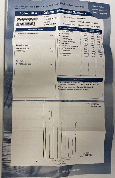
eCertificates of Performance | Agilent
It’s critical to not have an air leak anywhere in the system. Oxygen damage results in column degradation products going into the ion source, contaminating it. Oxygen also damages the filament. Tune evaluation may say <20 % water and <10 % nitrogen, but the goal is to have less than 1 % of water, nitrogen, and oxygen. See: Impact of Air Leaks on the Productivity of GC and GC/MS Systems
Symptom
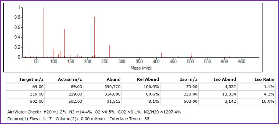
What if your spectrum shows high nitrogen but low oxygen? The example spectrum from a tune report shows 14.4 % N2 and only 0.5 % O2. Air is 78.09 % Nitrogen and 20.95 % Oxygen or approximately a 4:1 ratio. An air leak (4:1 ratio) would mean that either the O2 would be around 3.6 % or the N2 would only be 2.0 %.
There are three possible causes of the symptom:
- There is nitrogen contaminating the helium in the tank.
- There is a leak before the carrier gas filter, which is removing the oxygen.
- There is nitrogen coming from the carrier gas filter.
The system can’t preferentially extract nitrogen out of the air from a leak.
Troubleshooting
1. Contaminated Supply: When was the tank last replaced? If high nitrogen just happened after the tank was replaced, try a different tank first. Try a tank from a different batch or one that is known to be good on another GC/MS.
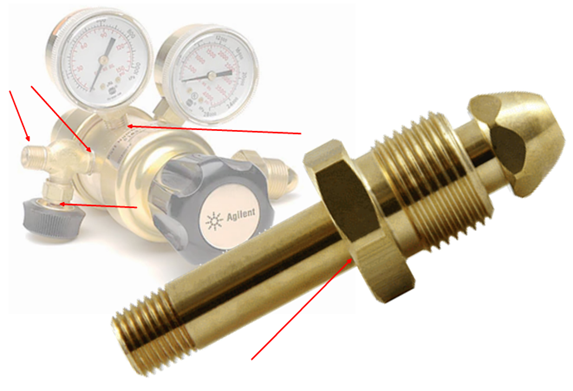
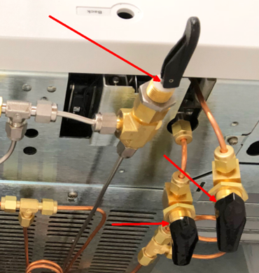
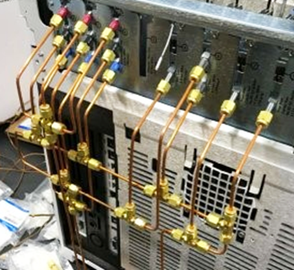
2 Leak before the gas filter: Do you have a helium leak detector like the Agilent G6693A? Use it on every connection and possible leak point from the tank itself to the back of the GC.

Make sure and use your leak detector at these possible leak points:
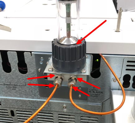
3. From the gas filter: Agilent carrier gas filters are filled with nitrogen gas during manufacturing. Helium can’t be used because the helium molecules are so small that they diffuse out easily and would be lost during shipment or storage, allowing air to diffuse in and ruin the trap. The filters have porous packing material that is coated with compounds that will capture specific gas contaminants, like H2O, O2, and hydrocarbons. There is nitrogen in the pores and interstitial spaces that must be removed. The pores are small, and many are unswept, dead-ends, cul-de-sacs, blind alleys, where just purging the filter with helium won’t remove the nitrogen molecules.


Nitrogen is removed by flushing and pressurization/depressurization cycles. See pages 34 – 35 in the Gas Clean Filter System User Manual. If that process does not sufficiently remove the nitrogen these steps may help. This is also used to flush the Bourdon tube that is part of most analog pressure gauges including the ones on the tank regulators. If you can hear the hiss of the gas flowing, it’s more than a liter per minute and that’s a good flush flow. Flush the regulator and the tubing to the gas filter before connecting the filter or installing the filter element the first time. Then flush the filter or filter element before making the final connection at the back of the instrument.
- Turn on Tank, turn off shutoff valve. It's best to have that shutoff valve plumbed immediately behind the instrument.
- Adjust pressure on the regulator to 80 to 100 psi
- Open shutoff valve
- Turn off tank - gauge will fall <let it fall all the way to ambient pressure
- Close shutoff valve
- turn on tank - gauge will rise <let it rise to the regulator setpoint
repeat 1 through 4 eight to ten times
- Set appropriate regulator pressure - Normal EPC 100 psi max, High Pressure EPC 150 psi max, CI gas 20 psi max.
Connect the filter and flush by allowing the gas to flow out into the laboratory, ten to fifteen minutes or more is typical. This basic flush will remove most of the nitrogen, but not all of it. Follow the directions above to pressure cycle the gas filter. This will help remove the nitrogen from the unswept areas.
The same result will not occur by just pushing your thumb over the exit and letting it build up pressure and then blowing out. Depressurizing to ambient on every cycle is necessary. The last time make sure that the exhaust valve and supply valve are both opened and connect the gas supply to the GC.
There may be a small amount of residual nitrogen that will go down with use of the instrument. Monitor the tune reports and inspect the filters regularly. Replace as necessary.
Gas Clean Filter - see: GasCleanFilter_5973-1528.pdf (agilent.com)
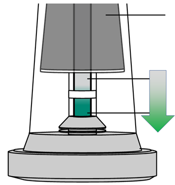
Indicator changes color from the top down (The indicator color and consumed indicator colors are different for each type of filter)
If the indicating material changed color from the top down, there is a leak upstream of the filter in your gas line or your gas quality is poor. Check for leaks at the cylinder, regulator and fittings, and check the gas quality
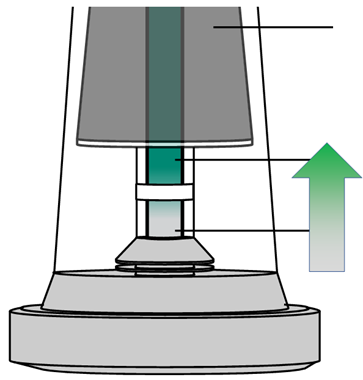
Indicator changes color from the bottom up
If your filter’s indicator changes color from the bottom up shortly after installation this indicates a leak downstream of the filter in your gas line. Check for leaks between the filter and the instrument.
.
.
.
.
.