

How Does Carrier Gas Flow and Vacuum Work Together in GC/MS
A diagram of the GC Split/Splitless inlet is shown. Gas is compressible, so to change the flows and pressures in the entire inlet subsystem quickly and accurately requires enough change or else the control feedback loop must work hard to be in control. When flows and pressures are small, it is difficult to change the flows or pressures in tiny percentages.
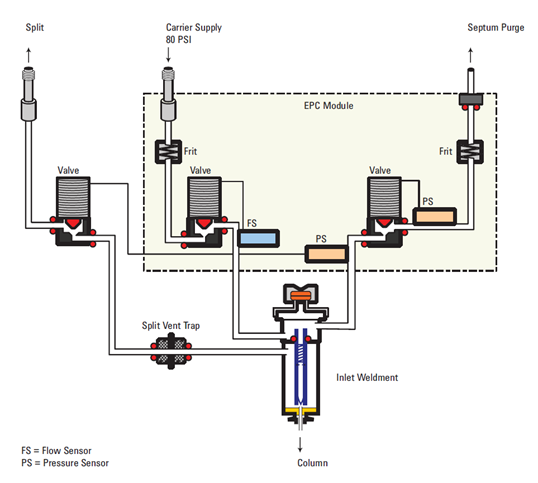
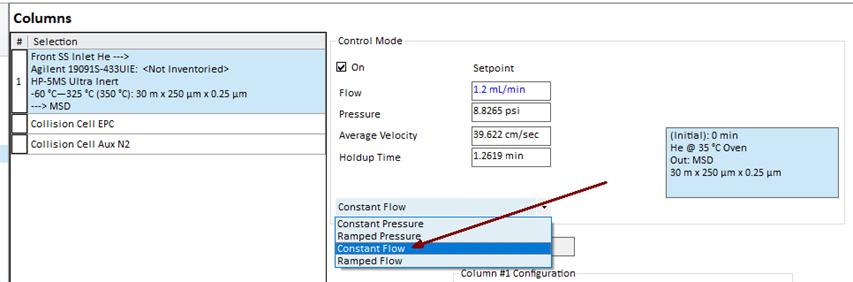
For good pressure and flow control the GC inlet pressure should always be >= 5 psi, no matter the carrier gas. Column dimensions, like smaller/wider bore or column length, and carrier gas type, can impact inlet flows and pressures. For example, using helium with a 30 m × 250 µm × 0.25 column at 35 °C oven and 1.2 ml/min = 8.83 psi. That same column with 1.2 ml/min with hydrogen carrier results in only 1.15 psi inlet pressure. This lower pressure will result in poor flow dynamics and pressure control and lead to reproducibility issues.
For good pressure and flow control using the Multimode and Split/Splitless inlets, the ones most used with GC/MS systems, there should be at least 20 ml/min or more of total flow into the injection port subsystem. Total flow is calculated and shown in the Acquisition Software and on the GC display.
Column Flow + Septum Purge Flow + Split Vent Flow = Total Flow
Helium Column Flow into the GC/MS is typically 1.2 ml/min, Septum Purge Flow is 3.0 ml/min, so the lowest Split Vent Flow that should be used is 15.8 ml/min (1.2 + 3 + 15.8 = 20 ml/min). If the total flow is too low, oxygen from the air can diffuse into the system and will damage the column.
The GC Calculators: Vapor Volume Calculator, Pressure Flow Calculator, and Solvent Vent Calculator, are available for download: GC Calculators and Method Translator Software | Agilent. They are also embedded in the GC driver used in MassHunter acquisition software for GC/MS systems and OpenLab CDS Acquisition software.
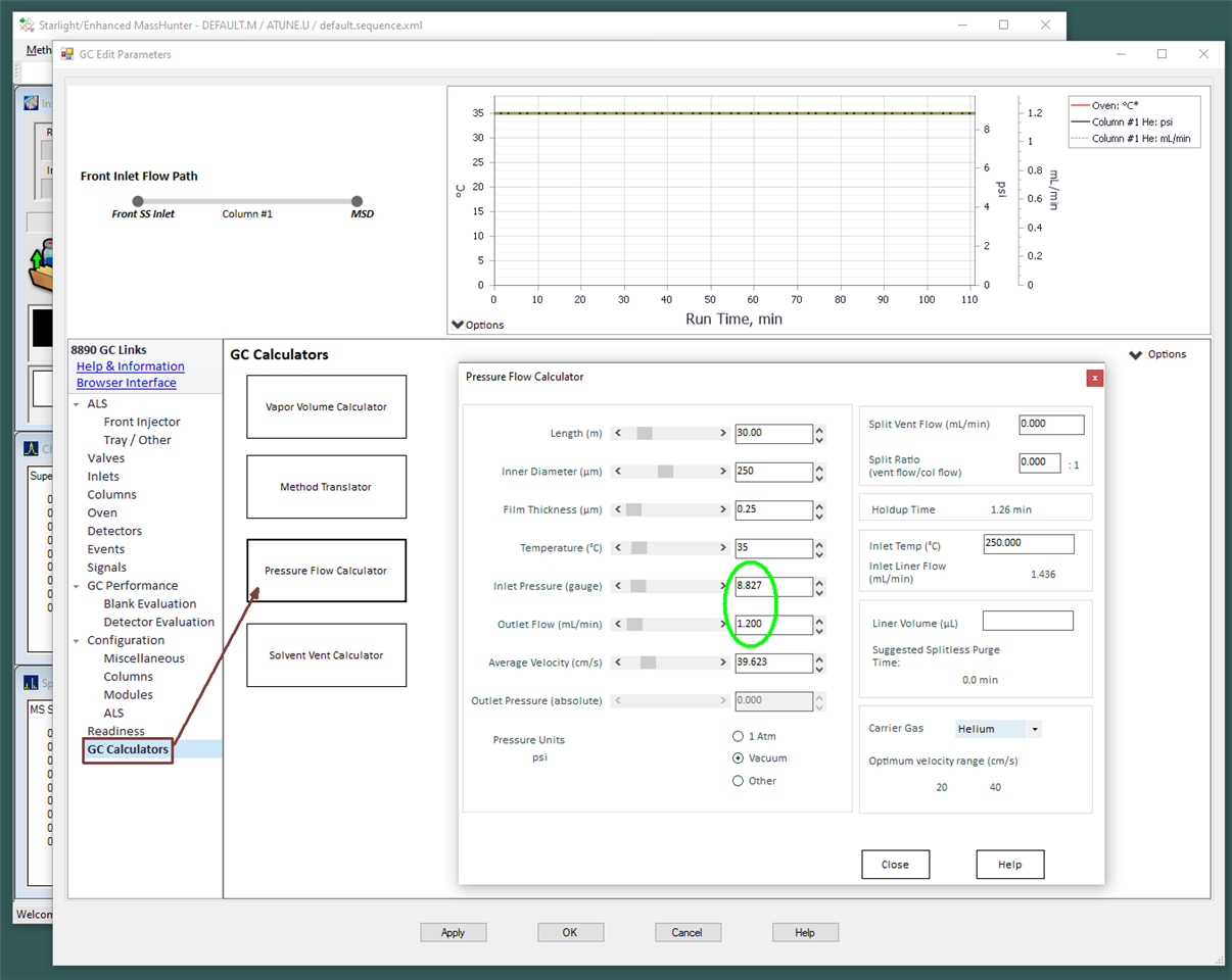
The screen capture illustrates an example of the GC Calculators in the GC driver, which is available in the Method Editor. The Pressure Flow Calculator can be used to decide which column to install, what happens to the flows during the run, what restrictors could be used with a splitter, what changes must be done when converting to hydrogen carrier gas, and more.
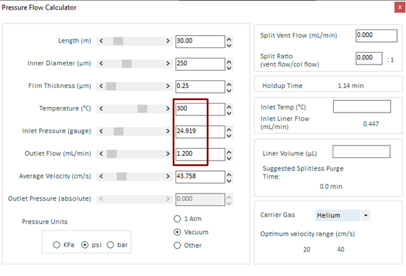
In this example, at 300 °C oven temperature, the inlet pressure must be up to 24.919 psi to maintain 1.2 ml/min.
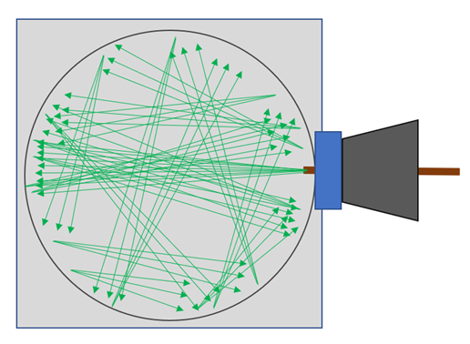
Mass Spectrometers operate best with a constant flow of carrier gas coming out of the column. It is molecular flow, which means that ions that are moving in one direction keep moving in that direction until they hit something or are hit by something.
The molecules flying out the end of the column are like a 0.25 mm diameter flashlight beam. With constant flow, the number of ions and molecules bouncing around is stable, which means the vacuum is stable, so the sensitivity and response is more stable. Imagine 400 billion molecules in there going ~2500 mph in every direction already and then adding billions and billions more every second.
The optimal helium flow into the ion source is 0.8 to 1.5 ml/min, and some say an even tighter range of 1.1 to 1.3 ml/min. Higher or lower flow will work but will not result in optimum response or sensitivity. The physical properties of the components, the design of the ionization chamber, filaments, lens locations, lens voltage ranges, surface finishes, detectors, and more, were all chosen with the optimum flow in mind.
The GC inlet pressure must change during the run as the column oven temperature is increased to get sample peaks to elute. Remember the ideal gas law, PV=nRT. Excellent system control of the inlet pressure maintains the optimal flow into the ionization chamber. All you must do is have the system properly configured and select Constant Flow.
Note: Properly configured means that the specified gases are plumbed, the regulators are on and set, the modules have the correct gases selected, and the column that is installed is selected and configured to the correct injection port and outlet. (In MassHunter acquisition software for GC/MS systems Help, see Columns Configuration Controls.) If the head of the column is trimmed frequently for maintenance, calibrate the column rather than relying on the length listed on the column tag.
In the molecular flow regime inside the mass spectrometer, the absence of collisions between molecules translates into the fact that high-vacuum pumps (turbomolecular and diffusion) do not "suck" gases, they simply generate some probability that once a molecule enters the pump it is permanently removed from the system. So it is only probability….chance? …luck? … that molecules/ions/particles get directed into the high vacuum pump and are moved away into the lower vacuum regime of the rough pump.
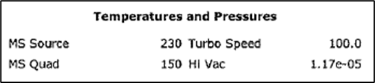
The vacuum is required to maintain a mean free path, to minimize the number of collisions and give enough space for the ions to move from where they are made to where they are detected. Most GC/MS single quad systems operate from ~7x10 e-6 to ~4x10 e-5 or so with 1.2 ml/min of helium column flow. The vacuum gauge reading can vary as much as 30 %. The vacuum reading can be seen on the acquisition main screen HiVac monitor, in the Manual Tune window, and is printed on all tune reports.
1.2 ml/min of helium carrier gas delivered at a constant flow rate into the vacuum system and the ion source of a GC/MS is optimal.
DE64241023
.
.
.