Inlet cooling

Hi,

I noticed something strange with the cooling of my Inlet, when my oven starts cooling my Inlet heats up. 

The cooling of my Inlet is working fine when I test it separately, but when my gc oven starts to cool the Inlet is not able cool further down or stay at a set temperature. 

Is normal for agilent systems? I don't have a lot of experience with agilent gc/ms systems, but I have never seen this on any kind of other gc/ms.

Its a gc 8890 with mmi, and compressed air as coolend.

Parents
  • Page 82 & 83 in the 8890 Operating Manual - G3540-90014

       "Use cryo temperature behaves differently in Compressed air mode than it does in N2 cryo or CO2 cryo mode. In Compressed air mode, the air coolant is used to cool the inlet regardless of the Use cryo temperature setpoint during the cooling cycle. If the inlet reaches setpoint, the air coolant is turned off and stays off. If the oven temperature is high enough, or the inlet was very hot previously, it is possible that the inlet temperature will rise and the GC will go not ready. For this reason, it is better to set the instrument cooling configuration as N2 cryo, or CO2 cryo, using compressed air as the coolant. Using compressed air, the LN2 hardware cools the inlet faster than the LCO2 hardware. Never use LCO2 or LN2 as your coolant while the instrument is configured in Compressed air mode."

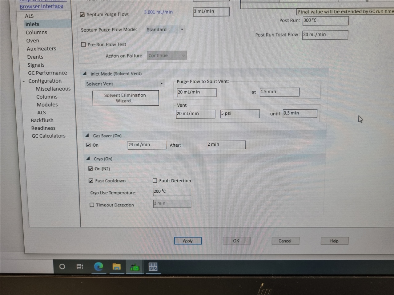
  • Yes I have seen this as well. The instrument is configured as N2 cryo. 

    I'm thinking that there is some setting in the software or method wrong.

    But during my measurements i do hear the valve click open at the set temperature but cooling goes very slow like it's  actually not using the cryo cooling at all.

    I have already send some screenshots to agilent of my method for help but according to them my settings are fine.

    Is there a other place in the method/software where you setup the cooling besides the oven tab?

    Screenshot of my method.

  • Could you please take a picture of the inlet cryo valve so that we can identify if the hardware is for liquid CO2 or N2?  You'll have to remove the rear top cover and the cryo valve is on the back left.

  • The problem has been solved in the meantime. With the installation of the system the service engineer installed the noise reduction filter for the inlet. This filter was blocking the airflow almost completely. After removing the filter the cooling is working perfectly.

    Thanks for the help and effort searching for the cause of the problem.

  • From the cryo inlet cooling restrictor installation guide:

    Requirements for compressed air cooling: • The compressed air should be free of particulate material, oil, and other contaminants. These contaminants could clog the valve or affect the proper operation of the GC. • Set the air supply pressure between 40 and 80 psig. • Use 1/4-inch copper or stainless steel tubing for supply tubing to the LN2 valve. When using the LN2 version at high supply pressures (typically >50 psig), a high frequency noise may be emitted from the instrument. To address this problem, a restrictor union G3510-27000 has been developed to reduce the emitted noise.

    Or reduce the air pressure to 40 to 50 psig...

Reply
  • From the cryo inlet cooling restrictor installation guide:

    Requirements for compressed air cooling: • The compressed air should be free of particulate material, oil, and other contaminants. These contaminants could clog the valve or affect the proper operation of the GC. • Set the air supply pressure between 40 and 80 psig. • Use 1/4-inch copper or stainless steel tubing for supply tubing to the LN2 valve. When using the LN2 version at high supply pressures (typically >50 psig), a high frequency noise may be emitted from the instrument. To address this problem, a restrictor union G3510-27000 has been developed to reduce the emitted noise.

    Or reduce the air pressure to 40 to 50 psig...

Children
No Data
Was this helpful?